![]()
![]()
![]()


|
|
|
|
M&G AIR PUMP A BRIEF EXPLANATION HOW THE SYSTEM WORKS
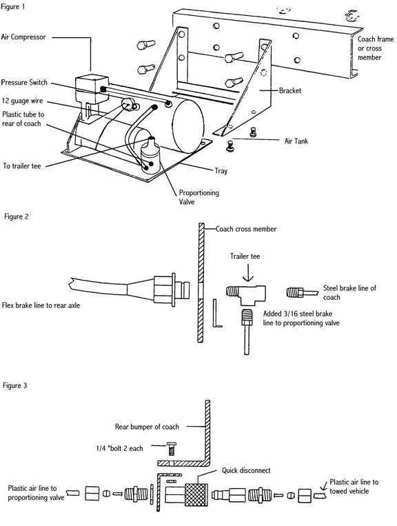
The M&G system, which is pneumatically operated, consists of five basic parts, as follows: 1. 12V air compressor 2. Air storage tank 3. Pressure switch 4. Proportioning valve 5. Air cylinder
The air compressor is controlled by the pressure switch, and keeps the air tank at a mean pressure. The proportioning valve is part hydraulic slave cylinder, and part air control valve. Pressure from the coach hydraulic brake system is fed through an added 3/16 steel line, to operate the slave cylinder of the proportioning valve. This, in turn, operates the air pressure controller section of the valve. The air pressure is directly related to the hydraulic pressure in the coach braking system, and is completely variable according to the hydraulic pressure being developed by the coach brake system. The M&G cylinder is mounted between the master cylinder and the vacuum booster on the towed vehicle. A 1/4 “ O.D. plastic (D.O.T. approved) air line runs from the proportioning valve to the M&G cylinder, with a quick disconnect located at the rear bumper area of coach. When the coach and the towed vehicle are being operated as a single unit, and the brakes are applied on the coach, the hydraulic pressure of the coach brake system operates the proportioning valve, and regulates the air pressure. The air pressure flows through the air line, and the brakes are applied on the towed vehicle as well as the coach. When the towed vehicle is being driven independently, there is no effect on the car’s braking system. It will operate in a completely normal manner.
INSTRUCTIONS FOR MOUNTING POWER PACK Locate a place on the right side of the coach toward the rear. Remove tray from the bracket. (See figure 1) Use bracket for template, and drill four 5/16” holes in frame. Mount bracket to frame or crossmember, using four 5/16 bolts. Install breather or filter to intake of compressor (gray or black plastic cylinder supplied). Replace tray in the bracket. Use locktite on tray bolts, and tighten. Remove the steel line from the bulk head fitting on frame (figure 2). Install tee fitting (trailer tee). Resecure steel line. Run a 3/16” steel line to the proportioning valve – cover the end of line to protect it from foreign material. Secure line from vibration. Be sure that the master cylinder is full of fluid, and the cap is tightly secure. During installation of the tee fitting, keep steel line upright, to keep fluid from running out. MAKE ALL CONNECTIONS AS QUICKLY AS POSSIBLE. To prevent loss of fluid. If this procedure is followed, it should be only necessary to bleed the fluid at the proportioning valve only. From the proportioning valve, run a ¼” plastic air line to the rear bumper area. Keep air line well away from any heat source. Secure. (See figures 1 & 3) Run a 12 gauge wire from an ignition or accessory source using a 30 amp fuse to compressor switch. Be sure drain valve is closed before starting compressor. Compressor shall not run over four minutes when tank is completely empty. Compressor shall not be used for any purpose other than operating M&G brake system. Use for any other purpose will void warranty.
Note : The air tank must be drained of moisture on a regular basis (once a week) , when the coach is driven. There may be some rust inhibitor expelled on the first few drains.
|
|
Berea Automotive Engineering Corp. Last modified: 03/27/08 |